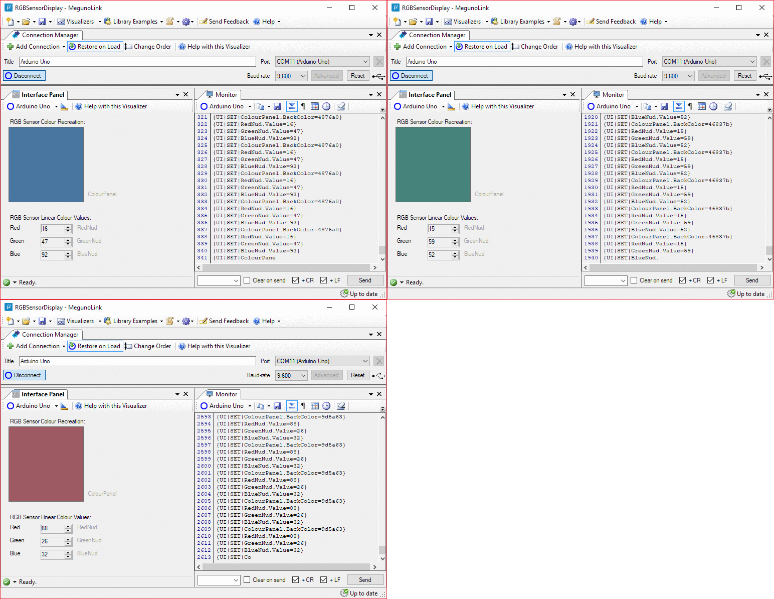
This example demonstrates how to control elements of a MegunoLink Interface Panel remotely. In this case, color is measured with a TCS34725 Red-Green-Blue (RGB) color sensor by an Arduino. The Arduino calculates the perceptual color and shows it on a MegunoLink interface panel.
Arduino-Driven Interface
MegunoLink Interface Panels are a handy way to control an Arduino program using buttons, sliders, textboxes, and other familiar GUI elements. However, Interface Panels can do more than send commands. Interface Panels can themselves be controlled by an Arduino program.
Driving the controls of an Interface Panel from an Arduino program allows for more advanced user feedback than LEDs or lines on a serial monitor. Many key properties of common controls such as progress bars, check boxes, numeric up/downs, text boxes, value lists, and more can be set at will. Simply use the InterfacePanel class in the MegunoLink Arduino library to send commands to an MLP UI Message Processor in an Interface Panel. It’s a lot faster to get up and running than developing a custom application, and allows all the logic for application and interface to be in one program. See the article on How to Update Interface Panel Controls from your Arduino for more details.

Controlling a MegunoLink Interface Panel over serial is a quick way to develop a responsive GUI for any Arduino Project.
This example takes colour measurements and displays them to the user. The measurements are represented in two ways, visually using a colour-changing square panel and numerically by three numeric up/down controls. The colour of the square panel and the values of the numeric controls are set by the Arduino program over serial every time a new colour measurement is made.
Additionally, UDP could be used instead of serial to allow a connection over a WiFi/Ethernet network. This is especially handy for controlling and receiving measurements from remote sensors.
Gamma Correction
One complication to displaying the colour measurements visually is gamma correction. In short, the sensor outputs measurements on a linear scale, but computer monitors output colour according to a nonlinear gamma scale. Gamma encoding is the process of converting linear colour intensity values to the gamma = 2.2 ‘power’ scale values that computer monitors expect. The onscreen colour measurement recreation wouldn’t look true-to-life without being gamma encoded first. More details in this article on gamma correction and in the gamma correction Wikipedia page.
Downloads
You can download a ZIP file containing the Arduino program and matching MegunoLink interface from this example below. This example also requires our Arduino Library.
Example Code
|
1 2 3 4 5 6 7 8 9 10 11 12 13 14 15 16 17 18 19 20 21 22 23 24 25 26 27 28 29 30 31 32 33 34 35 36 37 38 39 40 41 42 43 44 45 46 47 48 49 50 51 52 53 54 55 56 57 58 59 60 61 62 63 64 65 66 67 68 69 70 71 72 73 74 75 76 77 78 79 80 81 82 83 84 85 86 87 88 89 90 |
/* ********************************************************* * RGB Colour Display Example * * Controls the colour of a square panel and the values of * Red, Green, and Blue number displays on a MegunoLink * interface panel according to RGB colour sensor * measurements. Load the companion project: * "RGBSensorDisplay.mlx" into MegunoLink. * ****************************************************** */ //--------------------Includes------------------------- #include // Sensor library, install if missing: //"Sketch"->"Include Library"->"Manage Libraries"-> search #include "Adafruit_TCS34725.h" // Adafruit TCS34725 // MegunoLink library, install if missing as above. #include "MegunoLink.h" // Megunolink //--------------------Globals------------------------- // Create class instance for reading this colour sensor. Adafruit_TCS34725 ColourSensor = Adafruit_TCS34725(); // SCL to A5, SDA to A4 //--------------------Setup------------------------- void setup() { Serial.begin(9600); Serial.println("RGB Colour Display Example"); // Connect to Colour Sensor over I2C. Loop if can't. while (ColourSensor.begin() == false) { Serial.println("Sensor error, retrying"); delay(1000); } } //--------------------Loop------------------------- void loop() { // Read RGB colour measurements. uint16_t Red, Green, Blue, Nofilter; ColourSensor.getRawData(&Red,&Green,&Blue,&Nofilter); // Class instance for modifying properties of // controls on a MegunoLink interface panel. InterfacePanel UI; // Update numerical RGB display values. UI.SetNumber("RedNud", (long)Red); UI.SetNumber("GreenNud", (long)Green); UI.SetNumber("BlueNud", (long)Blue); // Gamma-encode the RGB values so the colour // recreation square looks the right colour on a // display. Maintain 0-255 value range. uint16_t RedEncoded = GammaEncode(Red, 2.2, 255); uint16_t GreenEncoded = GammaEncode(Green, 2.2, 255); uint16_t BlueEncoded = GammaEncode(Blue, 2.2, 255); // Convert binary numbers into hexidecimal strings. // Each must be two hex digits long. String RedHex = HexString(RedEncoded, 2); String GreenHex = HexString(GreenEncoded, 2); String BlueHex = HexString(BlueEncoded, 2); // Set ColourPanel Background Colour. // Colours can be by name or hex string. // Hex values need to be formatted RRGGBB. String RGBHex = RedHex + GreenHex + BlueHex; UI.SetBackColor("ColourPanel", RGBHex.c_str()); } //--------------------Functions------------------------- uint16_t GammaEncode(uint16_t LinearVal, float Gamma, uint16_t MaxVal) { float NormalizedVal = ((float)LinearVal)/MaxVal; float EncodedVal = pow(NormalizedVal, 1/Gamma); return (uint16_t)(EncodedVal * MaxVal); } String HexString(uint32_t Value, uint8_t MinmumDigits) { String WorkingString = String(Value, HEX); while (WorkingString.length() < MinmumDigits) {WorkingString = '0' + WorkingString;} return WorkingString; } |


