Create a custom UI for your garage door

Getting stuck out in the rain without keys was the motivation for this project. It uses an Arduino EtherTen to let you trigger a garage door opener. The Arduino hosts a website which you can visit using your Smart Phone to open, close and view the current state of your garage door.
With the Arduino connected to a wireless network, you can use your smart phone to connect to the webserver, enter a password, activate the garage door and get inside before getting drenched in the downpour.
A MegunoLink Pro interface panel is used to configure the program, setting up to 5 passwords, which are stored in the device’s EEPROM.
How does a Garage Door Work
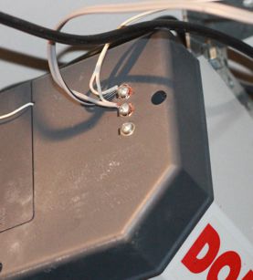
Many garage doors expose a couple of contacts that can be wired to a push button switch. This switch is often placed near a normal door and allows you to open and close the door as you enter or leave the garage without using a wireless remote control.
By adding a relay in parallel with this switch, an Arduino can be programmed to open and close the door.

Many garage door openers expose contacts for operation by manual switches.
How the Arduino Garage Door Opener Works
There are three key parts to the Arduino Garage Door controller:
- a serial interface for testing and setting passwords, and
- a web-interface for a user to control the garage door after entering a password
- a relay wired into the door opener to open/close the door when the Arduino receives the correct password
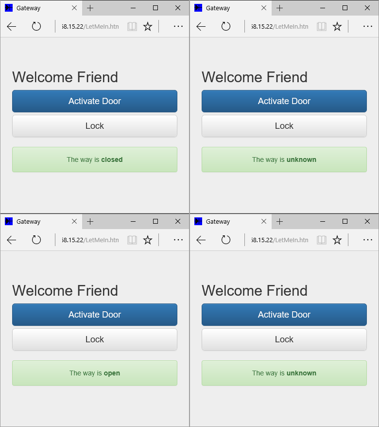
If you connect the Arduino to your wireless router, the web-interface will let you open and close the garage door with your smart-phone (or any web-browser). It presents a page to enter a password then, provided the user enters a valid password, a page to control the garage door.

The login and control pages for the Arduino garage door opener
Using a web-server to provide the interface means you don’t need to install a separate application on your phone. Normally, you’d install the Arduino garage door opener on your home network and give it a local IP address so that it can’t be accessed over the Internet.
Make sure that your wireless network is configured with a strong password though. Otherwise anyone could connect and possibly open the door!
All the code for the garage door opener is in the project repository.
The Serial Interface
The garage door controller’s serial interface lets you set passwords and open/close the door using a MegunoLink interface panel. The Arduino decodes and processes serial commands using our command handler library.
Here’s a screen shot of user interface panel I built in MegunoLink. The interface panel (on the left) has buttons for the ListPass and ActivateDoor commands. And a text box + a button to set each of the password slots. Output from the Arduino (the password list, for example), are shown in a monitor visualizer (on the right).

Manage passwords using a MegunoLink interface panel.
Three commands are supported:
SetPass [password-slot] [password]: sets a password.
There are 5 password slots available (numbered 0 to 4). This commands puts the[password]into[password-slot]. Passwords are saved to the Arduino’s eeprom using our EEPROMStore library and restored when the program first runs.ListPass: lists all the passwords the garage door controller knows about.
This is helpful for testing, but you might like to remove it if unsavory people might get access to your Arduino.ActivateDoor: activates the garage door relay, opening or closing the door. Again, helpful for testing.
The serial commands are setup in the InitializeSerialCommands() function, which is called from the Arduino’s setup() function:
|
1 2 3 4 5 6 7 8 |
CommandHandler<> SerialCommands; void InitializeSerialCommands() { SerialCommands.AddCommand(F("SetPass"), Cmd_SetPassword); SerialCommands.AddCommand(F("ListPass"), Cmd_ListPasswords); SerialCommands.AddCommand(F("ActivateDoor"), Cmd_ActivateDoor); } |
The command sent when a button is clicked is set on the button’s OnClickSend property in the “>interface panel designer. The commands set are shown in the table below. The ‘set password’ commands reference the text in the text boxes, where the user enters a password, using the notation [txtPass0.Text] etc. Each command ends with a newline character (\r\n). These are entered as \r\n.
| Button | Command |
|---|---|
| Activate Door | !ActivateDoor\r\n |
| List Passwords | !ListPass\r\n |
| Set Password 0 | !SetPass 0 [txtPass0.Text]\r\n |
| Set Password 1 | !SetPass 1 [txtPass1.Text]\r\n |
| Set Password 2 | !SetPass 2 [txtPass2.Text]\r\n |
| Set Password 3 | !SetPass 3 [txtPass3.Text]\r\n |
| Set Password 4 | !SetPass 4 [txtPass4.Text]\r\n |
Learn more about quickly building a user interface with MegunoLink by visiting:
The Web Interface
The Web interface is hosted using the Webduino web-server library. This library lets the Arduino serve simple web-pages. Accessing these web-pages through your smart-phone lets you login and open/close the garage door when your phone is on the same network as the garage door opener.
IP Address
Like any web-page, you need to have the Arduino’s IP address to make a connection. Normally, the browser looks up a web-sites IP address automatically using a domain name server. But the Arduino isn’t attached to a registered domain.
Instead we have to assign the Arduino an IP address and use that address in the web-browser.
The Arduino IP address is set using this line in the main program file GarageDoorOpener.ino:
|
1 |
IPAddress MyIPAddress( 192, 168, 15, 22); |
Unless you are going to setup routing, you need to make sure the Arduino has an IP address that is on the same sub-net as the device you want to use to access the garage door opener. The easiest way to do that is look up the private IP address of another device, such as your computer or phone, that is on the same network as the Arduino. It will probably have an IP address like 192.168.1.102. Create the IP address for your Arduino program from the first 3 groups of numbers and pick a different number for the last group. Each device on the network must have its own IP address, so pick a number for the last group that is much bigger or smaller than the one your other device has. For example 192.168.1.50 could be a good choice.
Here’s some links that can help:
- Find your Windows Computer’s Private IP Address
- Find your iPhone’s Wireless IP Address
- Find your Android Phone’s Wireless IP Address
The Web Pages
The web-interface is made up of three main pages:
- The home page which prompts the user to enter a password. This is the first page shown.
- The door controller page. This page is shown when the user enters a valid password. It lets authenticated users open/close the garage door and see whether the door is currently open or closed.
- The access denied page. This page is shown if a user enters an invalid password.
Here’s some screen shots of the default web-pages in a desktop web-browser:


After entering a password on the login page (left), the user will be shown the access granted page (middle) or the access denied page (right). Users who are allowed access can open/close the door and see the current status of the door.
Like all websites, the content for the pages uses the HTML language. This content is in the WebPages.cpp file in the Arduino project. It is sent to your browser when the main Arduino program calls one of the following functions in response to a web-request from your browser:
SendLoginPage: sends the page which requests a password from the userSendAccessGrantedPage: sends the page which allows an authenticated user to open/close the doorSendAccessDeniedPage: sent when a user enters an invalid passwordSendErrorPage: sent when the webserver on the Arduino detects an errorSendPageNotFound: sent when user requests an invalid page
When the user requests the login/home page, for example, the web-server sends:
|
1 2 3 4 5 6 7 8 9 10 11 12 13 14 15 16 17 18 19 20 21 22 23 |
<!DOCTYPE html> <html lang='en'> <head> <meta charset='utf-8'> <meta name='viewport' content='width=device-width, initial-scale=1, maximum-scale=1'> <meta http-equiv='X-UA-Compatible' content='IE=edge'> <title>Gateway</title> <link rel='stylesheet' href='https://maxcdn.bootstrapcdn.com/bootstrap/3.3.7/css/bootstrap.min.css' integrity='sha384-BVYiiSIFeK1dGmJRAkycuHAHRg32OmUcww7on3RYdg4Va+PmSTsz/K68vbdEjh4u' crossorigin='anonymous'> <link rel='stylesheet' href='https://maxcdn.bootstrapcdn.com/bootstrap/3.3.7/css/bootstrap-theme.min.css' integrity='sha384-rHyoN1iRsVXV4nD0JutlnGaslCJuC7uwjduW9SVrLvRYooPp2bWYgmgJQIXwl/Sp' crossorigin='anonymous'> <link rel='stylesheet' href='style.css'> <script src='https://code.jquery.com/jquery-3.1.0.min.js' integrity='sha256-cCueBR6CsyA4/9szpPfrX3s49M9vUU5BgtiJj06wt/s=' crossorigin='anonymous'></script> <script src='https://maxcdn.bootstrapcdn.com/bootstrap/3.3.7/js/bootstrap.min.js' integrity='sha384-Tc5IQib027qvyjSMfHjOMaLkfuWVxZxUPnCJA7l2mCWNIpG9mGCD8wGNIcPD7Txa' crossorigin='anonymous'></script> </head> <body> <div class='container'> <form action='LetMeIn.html' method='POST'> <h2>Speak Friend & Enter</h2> <input type='text' id='txtPassword' class='form-control' placeholder='Password' required name='message' autocomplete='off' /> <button class='btn btn-lg btn-primary btn-block' type='submit' name='send' value='Go'/>Login</button> </form> </div> </body> </html> |
Styling the Web-Pages
Styling affects how the page looks. Font sizes, button layout, etc.
The modern way to style web-pages uses cascading-style sheets, or CSS files. CSS files can contain named styles and styles for specific HTML elements, such as form or button elements. Styles contain everything from font size through to spacing between elements and animations.
Here are the styles defined for the Arduino garage door opener project:
|
1 2 3 4 5 6 7 8 9 10 11 12 13 14 15 16 17 18 19 20 21 22 23 24 25 26 27 28 29 30 31 32 33 34 35 36 37 38 39 40 41 42 43 44 45 46 47 |
body { padding-top: 40px; padding-bottom: 40px; background-color: #eee; } form { max-width: 350px; padding: 5px; margin: 0 auto; } h2 { margin-bottom: 10px; } input { margin-bottom: 10px; border-top-left-radius: 0; border-top-right-radius: 0; } .form-control { position: relative; height: auto; -webkit-box-sizing: border-box; -moz-box-sizing: border-box; box-sizing: border-box; padding: 10px; font-size: 16px; } .form-control:focus { z-index: 2; } .alert { margin-top: 20px; text-align: center; } |
And that is just a few simple attributes to layout the pages. Defining all the styles takes a lot of work. It can be hard to get everything just right because different browsers sometimes interpret things differently.
Most people use a framework nowadays to make things easier. A framework is a bit like an Arduino library: you install it and away you go! The framework developer takes care of all the nitty gritty details like making it work across different browsers.
Bootstrap is one of the most popular (free!) frameworks available at the moment. It was created by the folks who make Twitter, for developing responsive, mobile first projects on the web. Its not super important for the garage door project, but one of its best features is responsive layout. In a responsive design, the layout changes depending on the size of your device. Resize this dashboard theme to get an idea of what’s possible.
Did I mention its free?
You can download all the Bootstrap files and put them on your Arduino. Its not very large but every byte is precious on an Arduino with its limited memory. So instead of using the Arduino web-server on the garage door opener to supply the files needed for Bootstrap, we used a content delivery network.
A content delivery network is a site where content that is used by a lot of different people is stored. Aside from saving space on the Arduino by hosting the content for us, content delivery networks tend to be very fast and often use geo-replication to serve content from a computer that is close to the user.
So all that is needed to make Bootstrap available to layout our web-pages is these few lines in the <head> section of the HTML document. The SendHeader function adds this to the top of every page:
|
1 2 3 4 |
<link rel='stylesheet' href='https://maxcdn.bootstrapcdn.com/bootstrap/3.3.7/css/bootstrap.min.css' integrity='sha384-BVYiiSIFeK1dGmJRAkycuHAHRg32OmUcww7on3RYdg4Va+PmSTsz/K68vbdEjh4u' crossorigin='anonymous'> <link rel='stylesheet' href='https://maxcdn.bootstrapcdn.com/bootstrap/3.3.7/css/bootstrap-theme.min.css' integrity='sha384-rHyoN1iRsVXV4nD0JutlnGaslCJuC7uwjduW9SVrLvRYooPp2bWYgmgJQIXwl/Sp' crossorigin='anonymous'> <script src='https://code.jquery.com/jquery-3.1.0.min.js' integrity='sha256-cCueBR6CsyA4/9szpPfrX3s49M9vUU5BgtiJj06wt/s=' crossorigin='anonymous'></script> <script src='https://maxcdn.bootstrapcdn.com/bootstrap/3.3.7/js/bootstrap.min.js' integrity='sha384-Tc5IQib027qvyjSMfHjOMaLkfuWVxZxUPnCJA7l2mCWNIpG9mGCD8wGNIcPD7Txa' crossorigin='anonymous'></script> |
Bootstrap is then responsible for making the nice login button and the alert panel where the current door status is shown. Check out the Bootstrap website for tons of documentation on using their framework.
Status Updates
The web-browser on your phone gets the current state of the garage door (open, closed, or unknown) through status updates.
Web technologies are designed to scale thousands or millions of visitors. So when you request a page for a website, the server will send you that page then forget about you until you make the next request.
For our garage door opener project this means there isn’t really a standard approach for the Arduino to update the page you are looking at when the door opens or closes. But the door doesn’t move instantly. It would be nice to see the state change from closed to open on the page, without continually refreshing it.
Enter JavaScript. JavaScript is a programming language similar to the language we use to write Arduino sketches. Only instead of running on an Arduino board, it runs in your web-browser. Like just about all web-technologies, there are inconsistencies between browsers though so most people use a framework like jQuery.
Using JavaScript and jQuery the AccessGrantedPage asks the Arduino for the current state of the garage door and updates the page every couple of seconds. The code lives inside the webpage sent by the Arduino. The page looks like this; the parts that update the door state are highlighted:
|
1 2 3 4 5 6 7 8 9 10 11 12 13 14 15 16 17 18 19 20 21 22 23 24 25 26 27 28 29 30 31 32 33 34 35 36 37 38 |
<!DOCTYPE html> <html lang='en'> <head> <meta charset='utf-8'> <meta name='viewport' content='width=device-width, initial-scale=1, maximum-scale=1'> <meta http-equiv='X-UA-Compatible' content='IE=edge'> <title>Gateway</title> <link rel='stylesheet' href='https://maxcdn.bootstrapcdn.com/bootstrap/3.3.7/css/bootstrap.min.css' integrity='sha384-BVYiiSIFeK1dGmJRAkycuHAHRg32OmUcww7on3RYdg4Va+PmSTsz/K68vbdEjh4u' crossorigin='anonymous' type="text/css"> <link rel='stylesheet' href='https://maxcdn.bootstrapcdn.com/bootstrap/3.3.7/css/bootstrap-theme.min.css' integrity='sha384-rHyoN1iRsVXV4nD0JutlnGaslCJuC7uwjduW9SVrLvRYooPp2bWYgmgJQIXwl/Sp' crossorigin='anonymous' type="text/css"> <link rel='stylesheet' href='style.css' type="text/css"> <script src='https://code.jquery.com/jquery-3.1.0.min.js' integrity='sha256-cCueBR6CsyA4/9szpPfrX3s49M9vUU5BgtiJj06wt/s=' crossorigin='anonymous' type="text/javascript"></script> <script src='https://maxcdn.bootstrapcdn.com/bootstrap/3.3.7/js/bootstrap.min.js' integrity='sha384-Tc5IQib027qvyjSMfHjOMaLkfuWVxZxUPnCJA7l2mCWNIpG9mGCD8wGNIcPD7Txa' crossorigin='anonymous' type="text/javascript"></script> </head> <body> <div class='container'> <form action='LetMeIn.html' method='post'> <h2>Welcome Friend</h2> <button class='btn btn-lg btn-primary btn-block' type='submit' name='send' value='Activate Door'>Activate Door <a class='btn btn-lg btn-default btn-block' href='index.html' role='button'>Lock</a> <div class='alert alert-success'> The way is <span id='CurrentState' style='font-weight: bold;'>unresolved</span> </div> </form> <script type="text/javascript"> $(function() { function UpdateDoorState() { $.get('doorstate.json', function(data) { $('#CurrentState').text(data.DoorState); }); } UpdateDoorState(); setInterval(function() { UpdateDoorState(); }, 1500); }) </script> </div> </body> </html> |
The span tag on line 21, with an id of CurrentState, identifies the text on the page to update when the door state changes.
The script, starting on line 24, is a small program which updates the door-state using jQuery. Let’s break it down:
- A the top level is a container:
$(function() { … }). This is jQuery short hand to execute some code (the … bit) once the web-page is ready. It is shorthand for$(document).ready(function() { … });. This page is stored on the Arduino, so I used the shorter version to save memory. You can read more about running code when the web-page is ready. - Next a function
UpdateDoorState()is defined. This function does the real work. It requests the current door-state from the Arduino ($.get('doorstate.json'), …);). Then updates theCurrentStatetext on the page ($('#CurrentState').text(data.DoorState);) with the door state. This uses Ajax, a technology for web-pages to request updates to small portions of the page instead of requesting the whole page from the server every time something changes. Check out the jQuery Ajax documentation for more information. - Defining the function doesn’t execute it; that happens on the next two lines. Line 32 is a simple call to the
UpdateDoorStatefunction. This is called when the page is loaded to fetch the initial door-state. - Finally, line 33 sets up a timer (
setInterval(…)) that calls theUpdateDoorStatefunction every 1500 milliseconds (1.5 seconds).
That’s it. With this simple JavaScript/jQuery the page can poll the Arduino for the current state of the door and display it to the user.


The door status is obtained from the Arduino using an Ajax query
Hardware


There are a few different hardware options depending on you want just a basic garage door opener or you want to add door sensing. And how much you want to buy vs make.
At its heart, the garage door opener is an Arduino with an Ethernet connection and a relay module. So to get started you’ll want:
- An Arduino Etherten – Fully compatible with the the Arduino Uno, the Etherten includes an ethernet module based on the Wiznet chip used in the official Arduino shield. You could also use an Arduino Uno + Ethernet shield or the Arduino Ethernet board for this project.
- A relay breakout board. SparkFun have one and so does Banggood.com. Or you can build your own (see below).
- A box to keep everything tidy. We designed a custom case in Blender, printing it on an Up! Plus2 printer. You can download the design and print files from our Arduino boxes page. You can also find the files in the project repository
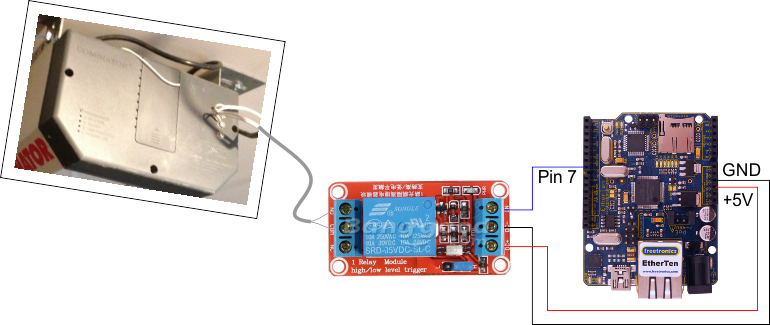
Wiring is straight forward. Just follow the diagram below.
- Digital output 7 from the Arduino connects to the signal-in pin on the relay module.
- DC+/+5V on the relay module connects to the 5V output of the Arduino board.
- DC-/GND on the relay module connects to the ground output on the Arduino board.
- The NO (normally-open) and COM (common) outputs on the relay module connect to the garage door opener. Be sure to check that the contacts on the door opener are low-voltage before attempting to make any connections.


Diagram for wiring the garage door opener with a relay module and EtherTen Arduino
Build your own Relay Breakout
If you don’t want to use a relay module, you can build your own relay breakout. You will need:
- A relay to activate the garage door opener. You’ll need one that can switch at 5V such as this one from SparkFun. Most garage door motors have a low-voltage switch near the internal door to the garage. The relay works in parallel with this switch so the Arduino can activate the door without disrupting normal operation. Make sure the switch on the garage door controller is low-voltage and safe before wiring anything up.
- A transistor to turn the relay on and off. Any small signal transistor should do the job, such as the 2N2222 or 2N3904.
- A diode across the relay protects the transistor when the relay turns off. The 1N4001 will do the job nicely.
Here’s the circuit diagram:


The garage door opener uses a relay to activate the door motor.
Add Door Position Detection
Its handy to know if the door is open or closed when you aren’t standing right in front of it.
There are a bunch of different ways to detect the door position, but I decided to mount Hall effect sensors on the guide rail and magnets on the chain.
Hall effect sensors detect the presence of magnets. I got some really strong neodymium magnets. The Hall effect sensor detects the magnets up to about 10 mm away from the sensor (it seems to depend on orientation of the magnet a bit) and I thought this would be easier to setup that trying to line up micro-switches.
So the parts for the door sensor are:
- 2 x Hall effect sensor: you can buy individual sensors such as the US1881 or get modules with the sensors mounted on small PCBs. The module is a bit more convenient as it gives you a ready made way to mount the sensor on the garage door rail.
- 2 x Magnets: I used round countersunk magnets, because we had them on hand. I tried larger ones as well, but they tended to make the chain jump across to the guide rail and stick them together!
- 1 x sensor mount: you could glue the sensors to the garage door rail, purchase a bracket from a hardware store, or use a 3D printer to make your own bracket. We opted for the last option. See below.
- 2 x magnet protectors: the magnets turned out to be very strong and brittle. They’d jump across the desk and break into little pieces when they hit a metal object. So I designed a small holder to protect them and built them using a 3D printer (see below).
- cable ties: zip ties proved a very convenient method to attach the sensor mount to the garage door rail and the magnets (inside the magnet protectors) to the door chain.
The 3D models for the magnet protectors and sensor mount were designed in OnShape. The models are available at this link. You’ll find STL files for printing in the project repository. Feel free to make a copy and adjust to suit your own door opener. You can export your changes as STL files for printing.


The mount model for sensors to detect the door position. It is attached to the door rail using zip ties.


The sensor mount is attached to the garage door opener rail with zip ties.


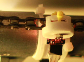
A small holder was printed to protect the magnets from breaking. The magnet is bolted inside and the holder is attached to the door chain using zip ties.
Mount the hall-effect sensors on the door rail and magnets on the chain. Position one magnet so that it is next to one sensor when the door is closed and the other magnet next to the second sensor when the door is open. Watch how the chain moves before attaching the magnets to the chain. Make sure the magnets won’t get trapped in the mechanism as the door opens and closes.
Following the wiring diagram below:
- The positive and negative pins on the sensor are connected to +5V and GND on the Arduino
- The signal output on the closed sensor is connected to pin 5
- The signal output on the open sensor is connected to pin 6
- When the door is open, position one magnet near the open sensor
- When the door is closed, position one magnet near the closed sensor


Wiring diagram for the door open/close sensors
Download Files
We made all the files you’ll need to build your own garage door opener available. Use the links below to find them.
- MegunoLink, a tool to support Arduino development. The interface panel for setting passwords was built using MegunoLink. The MegunoLink garage door opener project file can be found in the github repository.
- OnShape CAD files for 3D printed parts. You can clone this document and modify the design to suit your own installation.
- Github repository contains:
- Arduino source files
- MegunoLink project file (
Garage Door Password Manager.mlx) - STL files for 3D printed parts
Related Links
You’ll find more information here:
- Getting Started Building an Arduino User Interface with MegunoLink
- Interface Panel Documentation
- The Webduino WebServer library used in the garage door opener
- Bootstrap, the web-page layout library used by the garage door opener
- A step-by-step instructable for building your own Arduino garage door opener
-
Leave a Comment


What changes would be necessary to implement this using a wifi arduino board? Thanks.
Hi David, you would just need to find the equivalent classes on the wireless device and port it across.
Have you considered using a cheap garage door opener key fob?
Open it up, find the contact closure for open/close.
Use a relay to ‘click’ the button.
Interesting suggestion. I guess garage doors are designed to have this kind of switch interface so its pretty easy to retrofit in. Cheers Phil
Could you operate 3 or more doors with one device?
This project looks very interesting.
Thanks
I thought it posted this, but just in case
Can this be setup to work on 3 or more doors.
Interesting project, looks great
Thanks for sharing
Joe