The first step to viewing, plotting or sending serial data in MegunoLink is making a connection. MegunoLink can connect using serial, ethernet, WiFi or XBee Series 2 Pro hardware.
This page will help you get started making connections. It focuses on serial port connections over a USB cable, the most common type of connection. This is the connection used with the Arduino Serial library for commands such as Serial.println("Hello").
The connection manager is used to create and configure connections. A configuration panel is displayed for each connection; MegunoLink can connect to multiple devices at the same time.
Select Connection Manager from the visualizer tool or docker to open the connection manager. The configured connections are displayed in the new connection manager visualizer.

Open a connection manager from the visualizer menu to manage connections.

Create and configure serial, UDP, file and XBee connections with the Connection Manager
Add a Serial Connection
Use the Add Connection drop-down to add new connections. The drop-down lists all of the types of connection available.
Select the Serial Port item to create a new serial port. Or select one of the ports discovered on your computer to automatically configure the port for the new connection and save a step. Selecting one of the discovered ports does not prevent you from changing the port later on the configuration panel.
A new panel is added to the connection manager when you add a connection. The panel lets you configure the connection with configuration options suitable for the type of connection added.

Configure the Serial Connection
The Port and Baud-rate are the main settings that you need to configure for a serial connection.
Select the same Port that you are using to upload to your Arduino device. If you’ve installed our upload monitor, MegunoLink will automatically disconnect this port whenever the Arduino IDE uploads a new program.
Choose the same baud-rate that your Arduino sketch is using to start the serial port with the Serial.begin(…) command. This is normally in the setup() function. A common value would be Serial.begin(9600), but use whatever number your program is using.
The other settings on the serial configuration panel are:
- Name: the name of the connection. It is to help you keep track of multiple connections and can be anything you like. The name is displayed in the connection selector shown on visualizer toolbars.
- Port: the COM port the Arduino is connected to (see above).
- Baud-rate: the baud-rate your Arduino is using (see above).
- Connect/Disconnect: opens and closes the the connection to your device.
- Reset: restarts the program running on the Arduino for supported devices.
- Remove (❌): deletes the serial configuration panel.
Use the Advanced button to open additional serial configuration options when the port is closed. You can configure handshaking behavior and prevent MegunoLink resetting your Arduino device when the port is opened.

Configure the serial connection to your Arduino with the Connection Manager visualizer
Link connections to visualizers using the Connection Selector on the toolbar of every visualizer. Each visualizer processes data and commands for the selected connection.
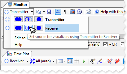
Select the connection linked to a visualizer by clicking the arrow to open the Connection Selector drop down. Select the connection you wish to use from the list of available connections. The buttons let you change the serial connection for other visualizers in one step:
- select
 to apply the new serial connection to all visualizers,
 - select
 to apply the new serial connection to any visualizer sharing the old connection,
 - select
 to update only the active visualizer.
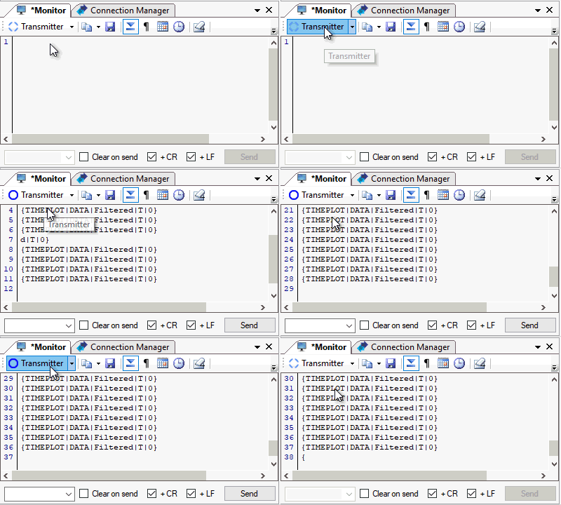
Click the Connection Selector button to connect and disconnect the serial connection.


Click the Connection Selection to open and close the serial connection.
Each serial connection can be used by any visualizer. You don’t need to create a separate connection for each visualizer. This lets you quickly change the physical COM port a connection uses without updating each visualizer separately.


